The current migration of optical fibers closer to homes and even into homes has increased the interest of service providers in new bend-optimized fibers (low bend fibers). To verify their usability, the two most promising types, trench-supported and nanostructured designs, have been considered and extensively investigated for their performance and compatibility with standard single-mode fibers. In particular, they have been intensively tested and evaluated for splicing, processing, mechanical properties, andoptical performances. 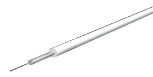
As a result, trench-supported and nanostructured fibers have been confirmed as good candidates for loss and bending critical applications (e.g. indoor cabling) due to their much higher immunity to bending losses and their high degree of compatibility
with standard single mode fibers.
Although optical fiber has superior signal capacity and immunity to electromagnetic interference, there is one fundamental aspect where fiber lags behind copper cables, and that is the signal loss when bent around tight corners.
This makes optical cable installation much more troublesome than electrical types, as they must be installed more carefully and with larger bending radii. Several ideas have been proposed to reduce the bending loss of single-mode fibers (SMF). These include (Figure 1) reducing the mode field diameter (MFD) while increasing the refractive index difference between the core and cladding glass [1], reducing the index of the cladding near the core region with/without reducing the cladding [2], adding a symmetrical ring of holes around the core [3][4], adding a low-index trench (fluorine-doped glass ring) [5]-[7], and introducing a randomly spaced nanostructured ring [8].
The industry has also responded to these recent innovations by introducing a new standard (ITU-T G.657; sections are shown in Table 1). The G.657 standard describes two groups of bend-optimized optical fiber types. The first is called Table A, which covers single-mode fibers that are fully compliant with the buried base of standard low water peak (G.652D) fibers, but offer a maximum macro bending loss of 0.75 dB per turn at 1’550 nm with r=10 mm. This is approximately 3 to 6 times lower bending loss than conventional SMF at this radius. The second recommendation, G.657 Table B, describes the performance of fibers with a maximum macro bending loss of 0.5 dB per turn at 1’550 nm with r=7.5 mm.
Fibers that meet G.657 Table B have approximately 15 to 30 times lower macro bending loss than conventional G.652D fibers at this radius. The Table B recommendation covers bend-insensitive fibers that may not be compatible with standard SMF, such as fibers with very small mode field diameters, reduced cladding, or hole-supported fibers. However, even the performance levels of G.657 Table B may not be sufficient for some embedded optical applications where full compliance with standard SMF is required and installers may want to staple and route optical cables around sharp corners without ducts or management elements. As a result, the standards organizations are currently discussing a new class ‘beyond Table B’
For indoor applications with a macro-bending specification as low as 0.1 dB/rev for a 5 mm radius at 1’550nm; Approximately 100 times lower macro-bending loss than a standard SMF.

Among the different low-warp fiber proposals described above (Figure 1), trench-supported and nanostructured fiber designs are the most promising approaches due to their potential warp performance (both claim to reach G.657B and above performance levels) and their compatibility with standard SMF. To actually verify this statement, we will focus on these fiber designs in the following text, perform different tests to simulate daily use, and compare them with standard SMF.

Mode field comparison: trench-assisted, nanostructured and standard SMF Reducing the bending loss can normally be done by increasing the refractive index difference between the core and the cladding. However, by doing this it is very difficult to maintain the mode field size and stay in a single mode at the same time. Trench-assisted and nanostructured approaches solve this problem by keeping the same core-cladding structure as standard SMF in the center but adding a low-index trench around the core (see Figure 2). Appropriate design of the location of this ring will only affect the tail of the optical field distribution (the main part causing the optical bending loss) without seriously changing the fundamental mode properties (e.g. mode field diameter, attenuation properties and dispersion properties). While still compatible with the standard G.652D range (8.6-9.5 μm), the resulting average value of the mode sizes becomes slightly different (9.2 μm for standard, 8.9 μm for trench-supported, and 8.6 μm for nanostructured fiber).
However, the theoretical optical coupling losses (assuming a Gaussian mode shape [9]) due to this mode size difference (0.3-0.6 μm) are negligible (less than 0.01 dB). Therefore, although the shape of the mode fields is not identical, the three investigated fiber types are largely comparable, and the ring types have the potential to allow bending around tight corners without a noticeable increase in attenuation.
For the following tests, all three types of fibers were used to produce 0.9 mm semi-tight conduits and 2.7 mm indoor simplex cables.
Bending Performance
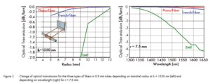
In general, the bending losses of any type of fiber decrease exponentially with bending radius and increase with operating wavelength. To determine the bending performance of all three types of fibers, standard bending loss tests (IEC 60794-1-2 E11A) were performed on 0.9 mm type tubes. Thus, the induced fiber attenuations in mandrels with different radii at selected wavelengths (see results at λ=1550 nm on the left of Figure 3) and the spectral loss for a mandrel of r=7.5 mm (on the right of Figure 3) were monitored. Both low bending fibers offer a greatly improved bending loss behavior compared to standard SMF and clearly meet the performance specification given in G.657 table B. As the measurements show, the trench-supported type can be bent up to r=10 mm while remaining below 0.1 dB per full turn up to 1625 nm wavelength, while the nanostructured fiber reached the same value for r=5 mm.
These measurements clearly show that these two low-bend fiber types can make fiber installations less critical and more flexible, as they allow bending around tighter corners.
Mechanical Properties
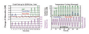
In addition to the poor treatment of optical fibers due to tight bending, they are frequently compressed and crushed during and after installation due to staples and other supporting features, and may have to withstand temperature changes. To check and compare the mechanical and environmental reliability of different fiber types, crushing tests (according to IEC 60794-1-2 E3) using 0.9 mm tubes and temperature cycling tests (according to IEC 60794-1-2 F1) using 2.7 mm cables were performed. Selected results are given in Figure 4.
Both low bend fiber types (even when protected with only 0.9 mm tubes) showed negligible loss increases for 1-minute compressive stresses up to 450 N/cm, in contrast to standard SMF (>0.4 dB). The temperature gradient test showed a similar behavior to the macro bend test. Even with very severe cooling (–40 °C), a moderate (<1 dB) increase in losses occurred for the nanostructured fiber (λ = 1550 nm). To some extent, higher losses (~5 dB) were measured for the trench-supported fiber.
However, both low bend fiber types outperform the standard SMF cable; this cable exhibits losses higher than 5 dB even at –15 °C (this indoor cable is specified between –20 and 70 °C at λ = 1300 nm).
The measurements confirm that in addition to macrobending, microbending performance (the main cause of loss during compressive stress) is also improved. They also allow the assumption that the nanostructure is not damaged (voids do not collapse/disappear) under mechanical pressure. Therefore, the use of low-bending fibers in the production of optical cables actually improves the optical performance under mechanical and environmental stress.
Splicing Research
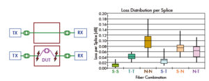
All indoor optical communication systems must connect to the old world, which typically operates using standard SMF. Typically this connection is accomplished by fusion splicing. However, low-bend fibers, even those that comply with G.652D, may not be seamlessly spliced to other standard SMFs due to mode shape mismatch, holes or voids in the glass, or different glass types within the fiber. To verify the splicability of the investigated low-bend fiber types, a systematic splice field test (Figure 5 left) was performed between and across all possible fiber combinations at a wavelength of 1310 nm. The measured results are summarized in Figure 5 (right) using box plots showing the average value (horizontal line), 75% (box) and 98% range (vertical line) of the obtained splice loss data (80 connections per set).
This plot shows quite clearly the variation in spliceability between the three different fiber types. The highest dispersion is that of the nanostructure fiber itself (0.04-0.18 dB), but theoretically (same mode field size of the two splice partners) a similar dispersion (0.0-0.03 dB) should be achieved with the standard SMF. This can be explained by a non-optimal setup of the splice device (no core, only cladding alignment can be used) and/or possible asymmetric collapse of the voids during splicing. In general, it is expected that with improved splicing techniques (recipes), performance levels will improve and even approach lower loss distributions similar to standard SMF splicing.
Although splicing performance is slightly worse on low-bend fibers, overall loss levels (average <0.1 dB, max <0.2 dB) are quite suitable for indoor applications where the higher losses are more than compensated for by the potential reduction in macrobend loss.
Connection Research
Connection to the outside world can be achieved by optical connectors as well as fusion splicing. Due to the different glass structures of the new low-bending fiber types, the question arose whether the end face would behave similarly to standard SMF during the assembly process and whether it would comply with geometric and quality criteria.
Manufactured 0.9 mm tubes containing three types of fibers were joined with LC-PC and SC-APC connectors using standard assembly processes (without knowing which type of fiber they were using). Fortunately, no special maintenance was performed or needed during the assembly process,
except for the visual inspection step, the unusual (but characteristic) end face appearance of the nanostructured fiber was noticed (see Figure 6 on the right).
Under 400x magnification, the nanostructured region is noticeable as colored dots, while the trench region is barely visible. When using white light for core backlighting, the coating region between the core and the trench and between the core and the nanostructure becomes visible as a faint light ring.
The measured end face geometries of the fiber core (radius, top offset, fiber protrusion) were not distinguishable between the different fiber types and were well within the tolerance range given by IEC 61755-3-1/2.
To better see the effect of polishing, cleaning and mating the connectors, a series of end faces (see Figure 7) were examined under a high-resolution scanning electron microscope (SEM). Looking at the images, it is clear that more scratches and marks are visible under SEM due to its excellent resolution down to the nanometer range.
However, the end faces still look very good, which proves the quality of the polishing process.
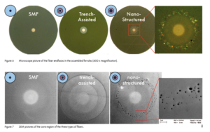
In these images, the loop of the trench-supported fiber is becoming apparent, and the nanostructures are now clearly distinguishable as submicron holes. Despite concerns that the holes might contain polish residue or other debris, or cause more scratches on the surface, the end surface appears to be as it should be. Closer inspection of the holes (see enlarged view at higher magnification) shows that their dimensions are actually in the nanoscale (<200 nm, compare to the 1 μm reference line below) and are randomly distributed.
In general, despite the differences between trench and nanostructure, it can be said that a standard assembly process can be used for both types of low-twist fibers without restrictions or adaptations (sealing, etc.).
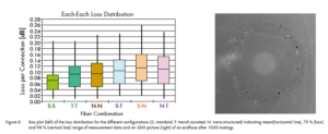
To demonstrate the compatibility of the bonded fiber assemblies, the loss distributions were investigated at λ = 1310 nm, similar to the splicing process. The results of splicing loss (LC-connector side) for all possible combinations are given as box plots in Figure 8 (left).
In contrast to the results obtained in the seasoning tests, the individual distributions are similar. The slightly higher average values of splicing loss of the low-twist fibers to SMF (S-T and S-N to S-S) can this time be partly explained by differences in mode shape. The higher average loss of the low-twist fibers to itself (T-T and N-N) than to SMF (S-S) again suggests that they may have slightly higher geometric tolerances (core eccentricity, fiber diameter) due to their more complex glass structure.
Finally, a mating cycle test (IEC-61300-2-2) consisting of 1000 reconnections was performed to check whether the nanostructures would be damaged after a series of connections. No loss degradation was noticed during testing. Although the end face was slightly damaged (more scratches, Figure 8 right) and there was some contamination (not properly cleaned), the nanostructured fiber behaved similarly to standard SMF.
Overall, despite slightly higher average values (0.11 dB instead of 0.07 dB), it can be said that the connector performance is consistent with standard SMF and is quite suitable for indoor applications.
Reliability Considerations
So far we have seen the benefits of using low bending fibers for optical cable installations. However, the signal transmission reliability of an installed optical link must be evaluated in terms of both optical loss and mechanical stability. With traditional rules for fiber management at large bend radii, fiber breakage has not been an issue. However, as fiber bend radii decrease, fiber life becomes an important consideration. Just consider that the stress on a fiber at a 5 mm bend radius is 4 times higher than that at a 10 mm bend radius and 40 times higher than that on a fiber following a traditional 30 mm bend radius.
Formulas for estimating the reliability of a fiber under a constant service stress (based on a power law for crack growth) are defined in the IEC 62048 standard. Given the same stress distribution along the fiber diameter, there is no physical reason to expect a different life rule among different fiber types. Applying this formula, the allowable fiber length was calculated to reach a life of 20 years with a failure probability of 1ppm depending on the bend radius (see Figure 9).
Despite slightly worse splicing performance for low bend fibers, the overall loss levels (average < 0.1 dB, max < 0.2 dB) are quite suitable for indoor applications where the higher losses are more than compensated by the potential reduction in macro bend loss. As a result, it was found that only 5 cm of fiber could be bent with a radius of 10 mm (not even a full turn) and only 1 cm of fiber could be bent with a radius of 5 mm (a little more than ¼ turn) to achieve these reliability levels (20 y, 1 ppm), in contrast to several 1000 m of fiber in distribution frames (fiber bend radius is limited to 30 mm with splice cassettes). As a result, tight bending of any type of fiber significantly reduces the connection reliability per turn, and the question arises as to what level of risk (how many sharp bends) is acceptable to the customer.
We recommend using trench-supported and nanostructured fiber types for bending and loss critical applications. However, to maintain system reliability, we recommend that the installation of low-bending fibers be treated with the same care as standard single-mode fibers and that appropriate fiber management be used.
Conclusion
The new trench-supported and nanostructured bend-resistant fiber types have been extensively tested and compared with standard single-mode fibers for their optical properties. They have been shown to perform better under bending, mechanical and environmental conditions, as well as being compatible to some extent with standard SMF. Normal manufacturing processes can be used to assemble connectors with these fibers, while achieving nearly similar optical performances.
On the other hand, the splicing of these fibers is more critical, resulting in slightly lower performance levels that can be overcome with further splicing and manufacturing process improvements. Despite the better bending performance and the great advantage in loss and bend critical applications, lifetime reliability under very stringent bending conditions still needs to be taken into account. Trench-supported and nanostructured fibers are recommended for bend and loss critical applications as they are a real improvement over current standard single-mode fibers, but should be treated with the same care as all optical glass fibers.
Note: For all the studies described above, we used Corning®’s SMF28® for standard SMF, Draka®’s BendBrightXS® for trench-supported fiber, and Draka®’s ClearCurve® for nanostructured design:
Corning®’s ClearCurve®, HUBER+SUHNER®’s CW-E9 for 0.9 mm pipes, and HUBER+SUHNER®’s CWJH-H27 for 2.7 mm cables.
